
- #ARDUINO NANO PINOUT ISP HOW TO#
- #ARDUINO NANO PINOUT ISP SERIAL#
- #ARDUINO NANO PINOUT ISP SOFTWARE#
The connection between the Arduino and the ATtiny is in essence the same, regardless of what Arduino one has.
#ARDUINO NANO PINOUT ISP HOW TO#
void pulse ( int pin, int times ) #ifdef USE_HARDWARE_SPI #include "SPI.Many sites already described how to use the Arduino as a programmer for the ATtiny series, but as some people still have some problems with it, it won’t hurt to share my experience in doing this with an Arduino Nano.

#ARDUINO NANO PINOUT ISP SERIAL#
To use 'Serial': #define SERIAL Serial #ifdef SERIAL_PORT_USBVIRTUAL #define SERIAL SERIAL_PORT_USBVIRTUAL #else #define SERIAL Serial #endif // Configure the baud rate: #define BAUDRATEđ9200 // #define BAUDRATEđ15200 // #define BAUDRATEđ000000 #define HWVER 2 #define SWMAJ 1 #define SWMIN 18 // STK Definitions #define STK_OK 0x10 #define STK_FAILED 0x11 #define STK_UNKNOWN 0x12 #define STK_INSYNC 0x14 #define STK_NOSYNC 0x15 #define CRC_EOP 0x20 //ok it is a space. // On the Due and Zero, 'Serial' can be used too, provided you disable autoreset. Due and Zero have an USB virtual serial port: 'SerialUSB'. // Leonardo and similar have an USB virtual serial port: 'Serial'. - it is more reliable because of USB handshaking. native USB port), if the Arduino has one: // - it does not autoreset (except for the magic baud rate of 1200). // Prefer the USB virtual serial port (aka. We must use pins that are broken out: #else #define RESET 4 #define LED_HB 7 #define LED_ERR 6 #define LED_PMODE 5 #endif // By default, use hardware SPI pins: #ifndef PIN_MOSI #define PIN_MOSI MOSI #endif #ifndef PIN_MISO #define PIN_MISO MISO #endif #ifndef PIN_SCK #define PIN_SCK SCK #endif // Force bitbanged SPI if not using the hardware SPI pins: #if (PIN_MISO != MISO) || (PIN_MOSI != MOSI) || (PIN_SCK != SCK) #undef USE_HARDWARE_SPI #endif // Configure the serial port to use. #define USE_OLD_STYLE_WIRING #ifdef USE_OLD_STYLE_WIRING #define PIN_MOSIđ1 #define PIN_MISOđ2 #define PIN_SCK 13 #endif // HOODLOADER2 means running sketches on the ATmega16U2 serial converter chips // on Uno or Mega boards. #ifndef ARDUINO_HOODLOADER2 #define RESET 10 // Use pin 10 to reset the target rather than SS #define LED_HB 9 #define LED_ERR 8 #define LED_PMODE 7 // Uncomment following line to use the old Uno style wiring // (using pin 11, 12 and 13 instead of the SPI header) on Leonardo, Due. #if defined(ARDUINO_ARCH_AVR) #if SPI_CLOCK > (F_CPU / 128) #define USE_HARDWARE_SPI #endif #endif // Configure which pins to use: // The standard pin configuration. Currently only for AVR, for other architectures (Due, Zero.), hardware SPI // is probably too fast anyway.
#ARDUINO NANO PINOUT ISP SOFTWARE#
divide target // f_cpu by 6: // #define SPI_CLOCK (128000/6) // // A clock slow enough for an ATtiny85 1 MHz, is a reasonable default: #define SPI_CLOCK (1000000/6) // Select hardware or software SPI, depending on SPI clock. for an ATtiny 128 kHz: the datasheet states that both the high and low // SPI clock pulse must be > 2 CPU cycles, so take 3 cycles i.e. // Put an LED (with resistor) on the following pins: // 9: Heartbeat - shows the programmer is running // 8: Error - Lights up if something goes wrong (use red if that makes sense) // 7: Programming - In communication with the slave // #include "Arduino.h" #undef SERIAL #define PROG_FLICKER true // Configure SPI clock (in Hz). A simple way to accomplish this is to power the complete system (programmer // and target) at 3V3. ) as // the programmer, make sure to not expose any of the programmer's pins to 5V. // IMPORTANT: When using an Arduino that is not 5V tolerant (Due, Zero. // Alternatively you can use any other digital pin by configuring // software ('BitBanged') SPI and having appropriate defines for PIN_MOSI, // PIN_MISO and PIN_SCK.

This will work even when not // using an Uno.

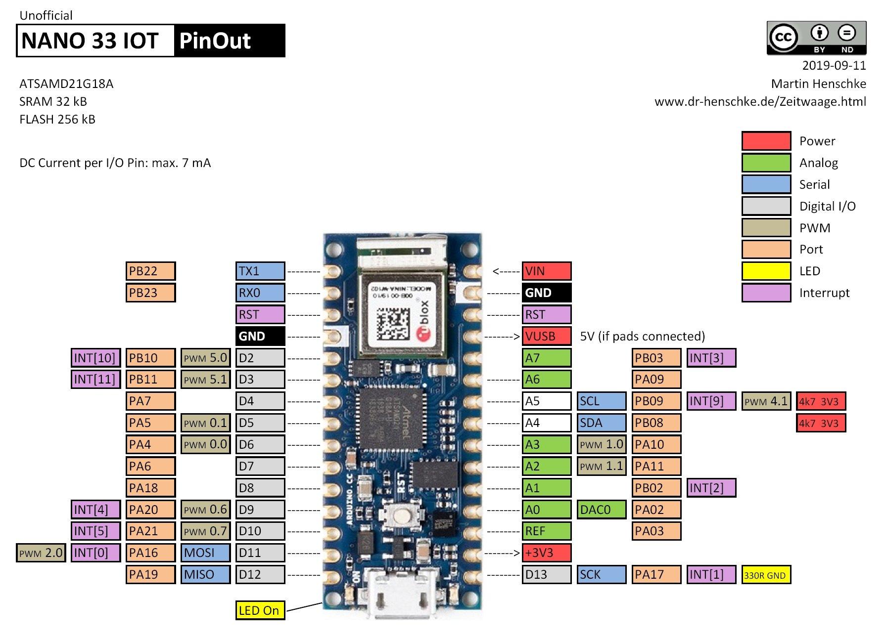
If you find this wiring more // practical, have a define USE_OLD_STYLE_WIRING. That is why many tutorials instruct // you to hook up the target to these pins. GND // // On some Arduinos (Uno.), pins MOSI, MISO and SCK are the same pins as // digital pin 11, 12 and 13, respectively. On all Arduinos, these pins can be found // on the ICSP/SPI header: // // MISO °. // By default, the hardware SPI pins MISO, MOSI and SCK are used to communicate // with the target. ArduinoISP // Copyright (c) 2008-2011 Randall Bohn // If you require a license, see // // // This sketch turns the Arduino into a AVRISP using the following Arduino pins: // // Pin 10 is used to reset the target microcontroller.


 0 kommentar(er)
